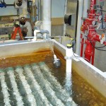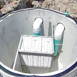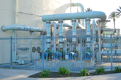
Life science exhibits house living aquatic species for public viewing at aquariums, marine parks, zoos and hotels. Regardless of the animal type, the provision and maintenance of clean water is a critical requirement. Within the life science market, there are three main application segments including the pre-treatment of water prior to being introduced to the exhibit, the monitoring of the exhibit itself, and the post-treatment of wastewater after its been removed from the exhibit. Exhibit tanks range widely in depth and capacity based upon the species, their requirements and the scenery such as rocks, plants, water features and backdrops. The support equipment is typically located behind the exhibit or hidden within the scenery. To maintain water quality and make up for evaporation, water is continuously circulated in and out of the exhibit. The post-treatment system receives wastewater from the exhibit, treats it to specification, removing physical or biological contaminants, and either recirculates it back into the exhibit or releases it to the municipal sewer or environment. A post-treatment system typically includes a storage tank to collect the wastewater, a neutralization tank to treat the wastewater and chemical feed tanks to supply the neutralization process. The storage tank can be above ground or below grade with an open or enclosed top, and is normally constructed of plastic, fiberglass or concrete. The neutralization tank is typically a plastic or fiberglass tank with an open or enclosed top and mixer for agitation. The chemical feed tanks are plastic day tanks, IBC totes or drums with enclosed tops. The primary requirement for this application is to monitor the liquid level in each tank, ensuring that the levels are maintained within their operational ranges, and either refilling the day tank or notifying the operator when additional chemical supply is needed prior to running out.
Technology
A short duration, high frequency ultrasonic sound wave is pulsed up to four times per second from the face of the transducer. The sound wave reflects off the surface of the liquid and returns to the transducer. The level sensor measures the time of flight between the sound generation and receipt, and translates this into the distance between the transducer face and liquid surface. The distance is then converted into a percentage of measured span and output as a proportional 4-20 mA signal.
Best Practices
The installed level sensor must have a clear view of the liquid surface. This means that the measurement space beneath the level sensor should be free of any obstructions such as pipes, fittings, walls or mixers inside the tank. The level sensor must be located above the highest liquid level and never be submersed during normal operation. Post-treatment systems can be indoors or outdoors, which depending upon the level sensor’s location and type of installation, may result in the formation of water droplets or ice on the transducer that can affect acoustic transmission and receipt. Where so, select a level sensor with an appropriate weatherproof enclosure rating and longer more powerful measurement range. Apply a very thin layer of Rain-X or petroleum jelly water repellant across the transducer face and locate the level sensor so it’s not directly exposed to weather. Liquid is normally dispensed into storage and neutralization tanks from the top and removed from the bottom. This typically creates an agitated liquid surface during filling and a smooth liquid surface during emptying. Additionally, the neutralization tank is often agitated with a mixer that may generate foam. Foam absorbs the acoustic signal and can reduce the effective measurement range of the level sensor. Where foam exists, the level sensor should be installed in a stand-pipe to separate out the surface foam from the point of measurement.
Installation
There are several ways to mount a level sensor in this application. Find a mounting location where the level sensor has a direct view of the liquid throughout the entire measurement span. The location must be flat, level to the liquid and accessible. The following equipment can be used to install the level sensor.
Tank Adapter
Tank adapters are recommended where the mounting location is level and not on a slope. Use a tank adapter that is slip x thread, and avoid thread x thread adapters. Do not use tank adapters that are mounted upside down.
Coupling
A shorter half coupling is preferred over a taller full coupling. Use a coupling that is slip x thread, and avoid thread x thread couplings. If you use a full coupling, it must follow the height and diameter restrictions described under Riser with Flange.
Riser with Flange
Long, narrow risers, which in fiberglass tanks may also extend a few inches inside the tank top, can affect acoustic transmission and receipt. The inner surface of the riser must be smooth and free of ridges, especially in the region below the installed transducer face. Risers with diameters of 3” or more are recommended. If the only option is a 2” diameter riser, the height of the riser and any mounting connections above it cannot exceed 5”. Caution should be taken with any riser heights greater than 8”, and the use of tee connections within the riser structure is not permissible.
Stand-Pipe
Level sensors can be installed in a stand-pipe to separate surface foam, dampen turbulence or maximize the acoustic signal strength of the level sensor. Do not use a stand-pipe in applications with dirty, coating or scaling liquids that will leave material build-up on the inner pipe wall. The stand-pipe must be one continuous section of smooth pipe without any breaks or transitions. The pipe’s inner diameter must be equal to or greater than the level sensors beam width and larger diameter pipes are recommended. To install the level sensor, mount a low-profile threaded coupling on top of the pipe. Just under the coupling, and within the level sensors dead band, drill two quarter inch vent holes on opposing sides of the pipe. The pipe should extend to the bottom of the tank, or at least below the level sensor’s measurement span. Cut a 45º angle on the bottom of the pipe. Finally, the level sensor should be maintained above the 45º cut, so there’s always liquid in the pipe.
Side Mount Bracket
The Flowline side mount bracket can be used to install the level sensor against the side wall of the tank or an aperture extended over the tank.
Center of Dome Top Tank
Where possible, avoid installing the level sensor in the center of a dome top tank. The dome top acts like a parabolic reflector that amplifies acoustic energy and may cause the level sensor to perform intermittently at certain tank levels.
Electrical
Post-treatment tanks may be located near large pumps, motors or variable frequency drives that can generate substantial EMI or RFI noise. Make sure that such devices are grounded to earth, and then ground the level sensor and associated electrical equipment to the same earth-ground as these devices. Some areas maybe subject to frequent lightning strikes or have un-reliable power. Where so, proper surge protection and filtering is recommended.
Span
The level sensor outputs a 4-20 mA current signal that’s proportionate to the measurement span within the tank. Users typically set the 4 mA to empty or the lowest measured level, and 20 mA to full or the highest measured level. Avoid placing the 4mA or 20mA span set points at or near levels where pumps, valves or alarms may actuate.
Interface
The level sensors 4-20 mA current signal is normally connected to a local controller or centralized control system. These devices may include a PLC, SCADA, DSC or stand-alone level controller. Either control device is fine as long as it accepts a 4-20 mA current signal. The operational range of the controller must then be programmed to match the measurement span of the sensor, and take into account that the sensors 4 mA set point is normally placed above the empty tank condition. Once the controllers operational range has been configured to the correct levels and engineering units, then the relay set points are applied for pump, valve or alarm automation. Remember, the primary control for this application is to monitor the liquid level in each tank, ensuring that the levels are maintained within their operational ranges, and either refilling the day tank or notifying the operator when additional chemical supply is needed prior to running out. An independent high and low level alarm or safety shut off system should always be used in addition to the primary system.