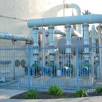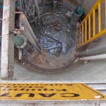
Stormwater lift stations collect rain and melting snow or ice from urban streets and highways to control flooding, reclaim water and protect the environment. If it washes down a street drain, it ends up in a stormwater lift station. Lift stations are below grade, gravity fed cylindrical or rectangular sumps, constructed of concrete or fiberglass with depths ranging from 6 to 30 feet. When full, they transfer their contents, and are typically daisy chained together to create a liquid highway through which stormwater can be transported over miles. The final destination is normally a pond, reservoir, treatment plant or the ocean. There are three main application segments in the lift station market including industrial wastewater, municipal sewer and municipal stormwater. Stormwater enters lift stations from the top and is removed from the bottom using two or more transfer pumps. The pumps are typically submersed within the sump or located next to the lift station in a pump house. Lift stations are crowded, dynamic environments with ladders, pipes, pumps, rails, electrical, sensors and water streams pouring in from one or more sources. Stormwater can be dirty or oily with particulates, trash and debris, making it difficult to measure reliably. The primary requirement for this application is to monitor the liquid level, periodically transfer the stormwater from the lift station to another location, and prevent it from overflowing or running dry.
Technology
A pulse of microwave RF energy is emitted from the base of the probe antenna at the speed of light. The pulse reflects off the dielectric material in the surface of the liquid and returns to the antenna. The level sensor measures the time of flight between the pulse generation and receipt, and translates this into the distance between the antenna and liquid surface. The distance is then converted into a percentage of measured span and output as a proportional 4-20 mA signal.
Best Practices
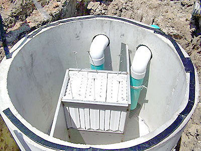
Stormwater lift stations are normally enclosed with a top, but can also be open and covered with safety grating. The installed level sensor must have a clear view of the liquid surface. This means that the measurement space beneath the level sensor should be free of any obstructions such as pipes, fittings, ladders, electrical, submersible pumps, water streams or large trash and debris. The level sensor must be located above the highest liquid level and never be submersed during normal operation.
Installation
For many, the product of choice in this application is the LR30 level sensor. Select the LR30 level sensor for below grade installation, bracket mounted to the sidewall or an aperture inside the lift station, or mounted using conduit. Find a mounting location where the level sensor has a direct, unobstructed view of the liquid throughout the entire measurement span when the sump is empty. The location must be flat, level to the liquid and accessible. The following equipment can be used to install the level sensor.
Bracket
The LR30 level sensor comes with an adjustable stainless steel bracket that’s typically bolted to the sidewall or an aperture within the lift station. This is the recommended method of installation.
Conduit
Alternatively, the LR30 level sensor can be mounted on rigid conduit, attached to its 1” MNPT connector. But caution must be taken to ensure that the sensor is properly positioned, affixed and will not move.
Electrical
Stormwater lift stations may be located near large pumps, motors or variable frequency drives that can generate substantial EMI or RFI noise. Make sure that such devices are grounded to earth, and then ground the level sensor and associated electrical equipment to the same earth-ground as these devices. Some areas maybe subject to frequent lightning strikes or have un-reliable power. Where so, proper surge protection and filtering is recommended.
Span
The level sensor outputs a 4-20 mA current signal that’s proportionate to the measurement span within the lift station. Users typically set the 4 mA to empty or the lowest measured level, and 20 mA to full or the highest measured level. Avoid placing the 4mA or 20mA span set points at or near levels where pumps or alarms may actuate.
Interface
The level sensors 4-20 mA current signal is normally connected to a local controller or centralized control system. These devices may include a PLC, SCADA, DSC or stand-alone level controller. Either control device is fine as long as it accepts a 4-20 mA current signal. The operational range of the controller must then be programmed to match the measurement span of the level sensor, and take into account that the sensors 4 mA set point is normally placed above the empty sump condition. Remember, the primary requirement for this application is to monitor the liquid level, periodically pump down or transfer the stormwater from the lift station to another location, and prevent it from overflowing or running dry. Once the controller’s operational range has been configured to the correct levels and engineering units, then the relay set points are applied for pump or alarm automation. Where two or more pumps are involved, users typically apply lead-lag and alternating pump control logic to maximize pump efficiency and life. An independent high and low level alarm or safety shut off system should always be used in addition to the primary system.