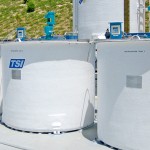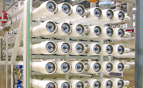
Ultrapure or high purity water has been purified to tight specifications to remove contaminants that can negatively affect people, products or equipment. These may include organic or inorganic compounds, bacteria, toxins, particulates and gases. Ultrapure water is widely used in the semiconductor, electronic, medical, pharmaceutical, biotech and food industries. Reverse osmosis and deionized water systems are different water purification processes. Reverse osmosis is a filtration method that removes molecules and ions from water as it passes through membranes. Deionization is a chemical method that uses specialty resins to exchange hydrogen and hydroxide ions for dissolved minerals, and then recombine them back into purified water. The ultrapure water that results from either process is contained in a storage tank for use in high purity applications. The storage tanks have two basic control systems, one to add liquid into the tank, and one to remove liquid from the tank into process. The primary requirement for this application is to monitor the liquid level, automatically refill the tank, and prevent it from overflowing or running dry.
Technology
A short duration, high frequency ultrasonic sound wave is pulsed up to four times per second from the face of the transducer. The sound wave reflects off the surface of the liquid and returns to the transducer. The level sensor measures the time of flight between the sound generation and receipt, and translates this into the distance between the transducer face and liquid surface. The distance is then converted into a percentage of measured span and output as a proportional 4-20 mA signal.
Best Practices
The installed level sensor must have a clear view of the liquid surface. This means that the measurement space beneath the level sensor should be free of any obstructions such as pipes, apparatus or walls inside the tank. Ultrapure water storage tanks are always enclosed and normally located indoors. Water is dispensed into the tank from the top and removed from the bottom. This creates an agitated liquid surface during filling and a smooth liquid surface during emptying. Some designs also recirculate water within the tank to prevent biological growth. Recirculation systems range from a trickle to prevent a static surface or a spray ball that affects a wide area. If a spray ball is present, select a level sensor with a longer more powerful measurement range, and position the level sensor or spray ball such that the level sensor, and the measurement space beneath the level sensor, is not within the spray pattern. If that’s not possible, install the level sensor in a stand-pipe to separate the spray from the point of measurement. If that’s not desirable, consider using a pulse radar level sensor.
Installation
There are several ways to mount a level sensor in this application. The inside of an ultrapure water storage tank normally has few obstructions. The tank top may be flat, domed, round or angled. Find a mounting location where the level sensor has a direct view of the liquid throughout the entire measurement span. The location must be flat, level to the liquid and accessible. The following equipment can be used to install the level sensor.
Tank Adapter
Tank adapters are recommended where the tank’s mounting location is level and not on a slope. Use a tank adapter that is slip x thread, and avoid thread x thread adapters. Do not use tank adapters that are mounted upside down.
Coupling
A shorter half coupling is preferred over a taller full coupling. Use a coupling that is slip x thread, and avoid thread x thread couplings. If you use a full coupling, it must follow the height and diameter restrictions described under Riser with Flange.
Stand-Pipe
Level sensors can be installed in a stand-pipe to separate the level sensor from spray. The stand-pipe must be one continuous section of smooth pipe without any breaks or transitions. The pipe’s inner diameter must be equal to or greater than the level sensors beam width and larger diameter pipes are recommended. To install the level sensor, mount a low-profile threaded coupling on top of the pipe. Just under the coupling, and within the level sensors dead band, drill two quarter inch vent holes on opposing sides of the pipe. The pipe should extend to the bottom of the tank, or at least below the level sensor’s measurement span. Cut a 45º angle on the bottom of the pipe. Finally, the level should be maintained above the 45º cut, so there’s always liquid in the pipe.
Riser with Flange
Long, narrow risers, which in fiberglass tanks may also extend a few inches inside the tank top, can affect acoustic transmission and receipt. The inner surface of the riser must be smooth and free of ridges, especially in the region below the installed transducer face. Risers with diameters of 3” or more are recommended. If the only option is a 2” diameter riser, the height of the riser and any mounting connections above it cannot exceed 5”. Caution should be taken with any riser heights greater than 8”, and the use of tee connections within the riser structure is not permissible.
Center of Dome Top Tank
Where possible, avoid installing the level sensor in the center of a dome top tank. The dome top acts like a parabolic reflector that amplifies acoustic energy and may cause the level sensor to perform intermittently at certain tank levels.
Electrical
Storage tanks may be located near large pumps, motors or variable frequency drives that can generate substantial EMI or RFI noise. Make sure that such devices are grounded to earth, and then ground the level sensor and associated electrical equipment to the same earth-ground as these devices. Some areas may be subject to frequent lightning strikes or have un-reliable power. Where so, proper surge protection and filtering is recommended.
Span
The level sensor outputs a 4-20 mA current signal that’s proportionate to the measurement span within the storage tank. Users typically set the 4 mA to empty or the lowest measured level, and 20 mA to full or the highest measured level. Avoid placing the 4mA or 20mA span set points at or near levels where pumps, valves or alarms may actuate.
Interface
The level sensors 4-20 mA current signal is normally connected to a local controller or centralized control system. These devices may include a PLC, SCADA, DSC or stand-alone level controller. Either control device is fine as long as it accepts a 4-20 mA current signal. The operational range of the controller must then be programmed to match the measurement span of the level sensor, and take into account that the level sensors 4 mA set point is normally placed above the empty tank condition. Once the controllers operational range has been configured to the correct levels and engineering units, then the relay set points are applied for pump, valve or alarm automation. Remember, the primary control for this application involves the filling of the water storage tank before it empties, thus avoiding shutting down the process due to lack of supply. This is typically done with a pump or valve. The fill process should start at a low level pump on or valve open set point and stop at a high level pump off or valve closed set point. A low-level alarm or shut off set point should be placed under the pump on or valve open set point. An independent high level alarm or safety shut off system should always be used in addition to the primary system, and an independent low level alarm or safety shut off system is recommended for pump or process protection.