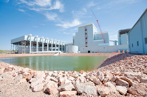
Reservoirs store large volumes of water and can be a natural or man-made lake, pond or impoundment structure. They can be gravity or pump fed. Reservoirs are typically created by controlling a stream that flows into a natural body of water, constructing a dam within a river valley, excavating a basin into flat ground or constructing an above grade retention pond. No matter the type, reservoirs play a critical role in water supply management, irrigation, flood control and public recreation. Reservoirs are commonly used to balance flow in river or stream networks, taking in and storing water during peak precipitation, and releasing water during dry periods. In-flow, storage and out-flow balancing is achieved by monitoring the reservoir level and weather forecasts, and releasing water ahead of large storms to free up capacity. Depending upon the reservoir type and size, they range from 3’ to 50’ in depth. The primary requirement for this application is to monitor the liquid level, balance the in-flow and out-flow, and prevent the reservoir from overflowing or running dry.
Technology
A pulse of microwave RF energy is emitted from the base of the probe antenna at the speed of light. The pulse reflects off the dielectric material in the surface of the liquid and returns to the antenna. The level sensor measures the time of flight between the pulse generation and receipt, and translates this into the distance between the antenna and liquid surface. The distance is then converted into a percentage of measured span and output as a proportional 4-20 mA signal.
Best Practices
Reservoirs are normally outdoors with large surface areas, and are fully exposed to the elements. There may be scaffolding or other structures that extend over the reservoir where a level sensor can be installed. The installed level sensor must have a clear view of the liquid surface. This means that the measurement space beneath the level sensor should be free of any obstructions such as pipes, fittings, walls or equipment in the reservoir. If surface ice forms within the measurement space, the level sensor will likely detect the top of the ice. The level sensor must be located above the highest liquid level and never be submersed during normal operation.
Installation
For many, the product of choice in this application is the LR30 level sensor. Select the LR30 level sensor for bracket mount installation to an aperture, suspended over the reservoir. Find a mounting location where the level sensor has a direct, unobstructed view of the liquid throughout the entire measurement span when the reservoir is empty. The location must be flat, level to the liquid and accessible. The following equipment can be used to install the level sensor.
Bracket
The LR30 level sensor comes with an adjustable stainless steel bracket that’s typically bolted to an aperture, suspended over the reservoir. This is the recommended method of installation.
Conduit
Alternatively, the LR30 level sensor can be mounted on rigid conduit, attached to its 1” MNPT connector. But caution must be taken to ensure that the level sensor is properly positioned, affixed and will not move.
Electrical
The level sensor may be located near large pumps, motors or variable frequency drives that can generate substantial EMI or RFI noise. Make sure that such devices are grounded to earth, and then ground the level sensor and associated electrical equipment to the same earth-ground as these devices. Some areas maybe subject to frequent lightning strikes or have un-reliable power. Where so, proper surge protection and filtering is recommended.
Span
The level sensor outputs a 4-20 mA current signal that’s proportionate to the measurement span within the reservoir. Users typically set the 4 mA to empty or the lowest measured level, and 20 mA to full or the highest measured level. Avoid placing the 4mA or 20mA span set points at or near levels where pumps, gates or alarms may actuate.
Interface
The level sensors 4-20 mA current signal is normally connected to a local controller or centralized control system. These devices may include a PLC, SCADA, DSC or stand-alone level controller. Either control device is fine as long as it accepts a 4-20 mA current signal. The operational range of the controller must then be programmed to match the measurement span of the level sensor, and take into account that the level sensors 4 mA set point is normally placed above the empty reservoir condition. Remember, the primary requirement for this application is to monitor the liquid level, balance the in-flow and out-flow, and prevent the reservoir from overflowing or running dry. Once the controller’s operational range has been configured to the correct levels and engineering units, then the relay set points are applied for pump, gate or alarm automation. An independent high and low level alarm or safety shut off system should always be used in addition to the primary system.