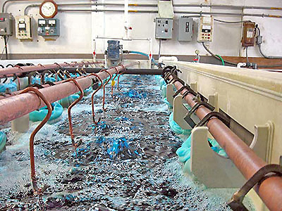
Plating or metal finishing is the process of depositing a metal coating on an object such as chrome, gold, silver, nickel or zinc. Plating improves the appearance, corrosion resistance, hardness and wear ability of parts. The most common plating processes are electroplating and electroless plating. Electroplating uses electric current to reduce dissolved metal cations to coat an electrode, and is primarily used to change the surface properties of metal parts. Electroless plating is a chemical technique that relies on the presence of a reducing agent, such as sodium hypophosphite that reacts with metal ions to deposit metal on plastic or metal parts. In either process, parts are dipped into a series of plating tanks or baths that clean, etch, plate and rinse coated parts to specification. Plating tanks are often rectangular, open top, plastic or fiberglass baths that are 3’ to 6’ in height. Normally placed in a row with common walls between each tank, plating systems can have as few as 3-4 tanks or as many as 30 tanks in a single line. Depending upon the system, parts are manually or automatically lifted, lowered, raised and moved from one tank to the next. Hence plating tanks, including the space required for parts dipping and movement are generally crowded, busy environments. The primary requirement for this application is to monitor the liquid level, ensuring that tank levels are maintained in a near full state without parts displacement, and a full state with parts displacement. So the two operational levels vary based upon the size or displacement of the parts to be plated.
Technology
A short duration, high frequency ultrasonic sound wave is pulsed up to four times per second from the face of the transducer. The sound wave reflects off the surface of the liquid and returns to the transducer. The sensor measures the time of flight between the sound generation and receipt, and translates this into the distance between the transducer face and liquid surface. The distance is then converted into a percentage of measured span and output as a proportional 4-20 mA signal.
Best Practices
The installed level sensor must have a clear view of the liquid surface. This means that the measurement space beneath the level sensor should be free of any obstructions such as pipes, fittings, walls or submersible heaters inside the tank. The level sensor must be located above the highest liquid level, never submersed during normal operation, and clear of parts or apparatus moving in and out of the tanks. This often results in the level sensor being located next to the side wall of the tank. Plating tanks are sometimes heated which may result in the formation of water droplets on the transducer that can affect acoustic transmission and receipt. Where so, select a level sensor with a longer more powerful measurement range, and apply a very thin layer of Rain-X or petroleum jelly water repellant across the transducer face. Depending upon the chemicals and amount of agitation, there may be pockets of surface foam. Foam absorbs the acoustic signal and can reduce the effective measurement range of the level sensor. Where significant foam exists, the level sensor should be installed in a stand-pipe to separate the surface foam from the point of measurement.
Installation
In this application, the level sensor is typically installed on a bracket or stand-pipe. Find a mounting location where the level sensor has a direct view of the liquid throughout the entire measurement span. The location must be flat, level to the liquid and accessible. The following equipment can be used to install the level sensor.
Side Mount Bracket
The Flowline side mount bracket can be used to install the level sensor against the side wall of the tank or an aperture extended over the tank.
Stand-Pipe
Level sensors can be installed in a stand-pipe to separate surface foam, dampen turbulence or maximize the acoustic signal strength of the level sensor. Do not use a stand-pipe in applications with dirty, coating or scaling liquids that will leave material build-up on the inner pipe wall. The stand-pipe must be one continuous section of smooth pipe without any breaks or transitions. The pipe’s inner diameter must be equal to or greater than the level sensors beam width and larger diameter pipes are recommended. To install the level sensor, mount a low-profile threaded coupling on top of the pipe. Just under the coupling, and within the level sensors dead band, drill two quarter inch vent holes on opposing sides of the pipe. The pipe should extend to the bottom of the tank, or at least below the level sensor’s measurement span. Cut a 45º angle on the bottom of the pipe. Finally, the level should be maintained above the 45º cut, so there’s always liquid in the pipe.
Electrical
Plating tanks may be located near large pumps, motors or variable frequency drives that can generate substantial EMI or RFI noise. Make sure that such devices are grounded to earth, and then ground the level sensor and associated electrical equipment to the same earth-ground as these devices. Some areas maybe subject to frequent lightning strikes or have un-reliable power. Where so, proper surge protection and filtering is recommended.
Span
The level sensor outputs a 4-20 mA current signal that’s proportionate to the measurement span within the tank. Users typically set the 4 mA to empty or the lowest measured level, and 20 mA to full or the highest measured level. Avoid placing the 4mA or 20mA span set points at or near levels where pumps, valves or alarms may actuate.
Interface
The level sensors 4-20 mA current signal is normally connected to a local controller or centralized control system. These devices may include a PLC, SCADA, DSC or stand-alone level controller. Either control device is fine as long as it accepts a 4-20 mA current signal. The operational range of the controller must then be programmed to match the measurement span of the level sensor, and take into account that the level sensors 4 mA set point is normally placed above the empty tank condition. Once the controllers operational range has been configured to the correct levels and engineering units, then the relay set points are applied for pump, valve or alarm automation. Remember, the primary control requirement for this application is to monitor the liquid level, ensuring that the levels are maintained in a near full state without parts displacement, and a safe full state with parts displacement. An independent high and low level alarm or safety shut off system should always be used in addition to the primary system.