
Chemical Distribution

Industrial Manufacturing

Industrial Water

Municipal Water

Dry Solids
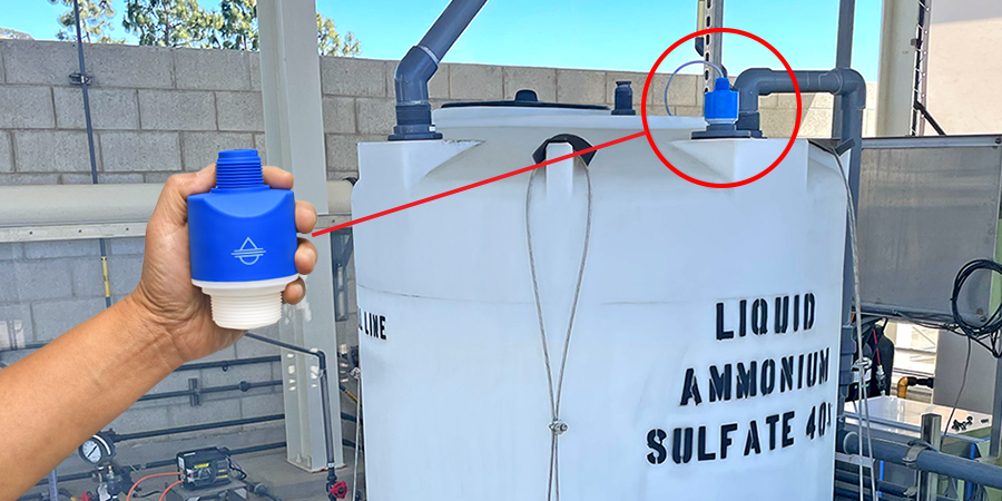
Non-Invasive Tank Radar Level Transmitter
When a Southeastern chemical distributor needed reliable NON-INVASIVE level measurement of their customer […]
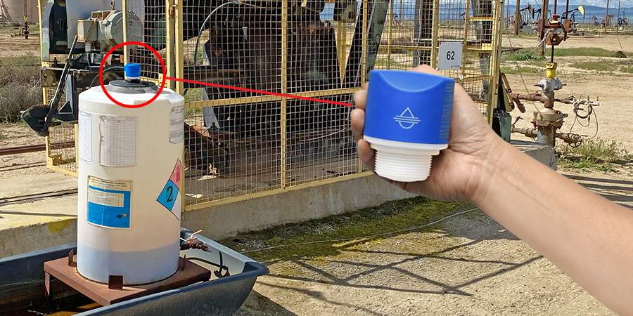
Oil Well Chemical Tank Radar Level Transmitter
When an Oklahoma oil company needed reliable level measurement of their corrosion and […]
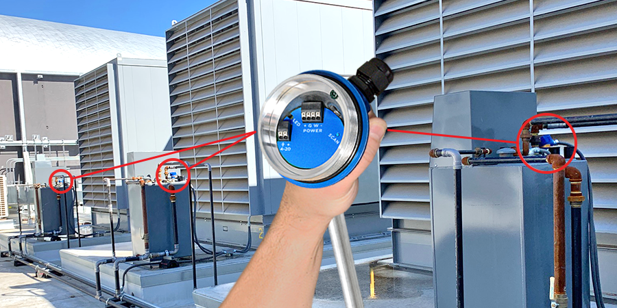
SOFI Diesel Generator Tank Guided Wave Level Transmitter
When SOFI Stadium needed reliable level measurement of their diesel generator tanks, they […]
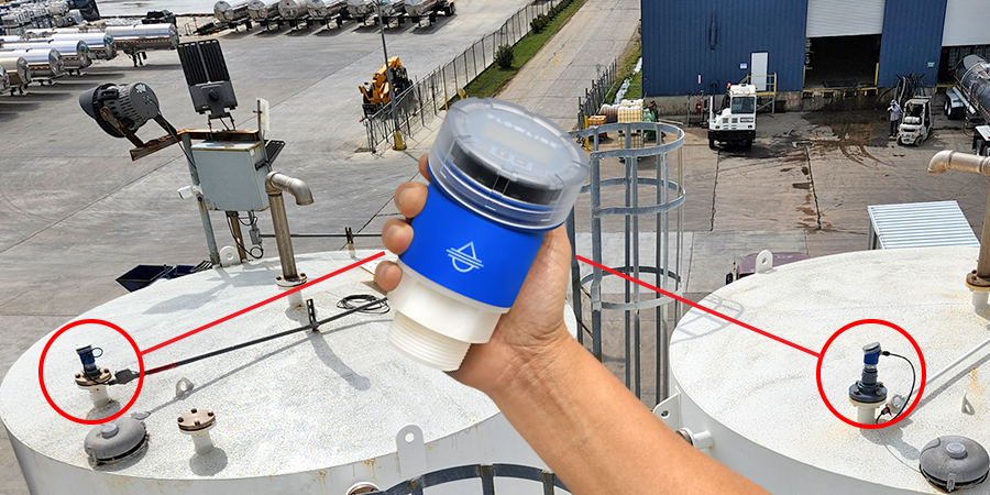
Chemical Storage Tank Radar Level Transmitter
When a Gulf Coast chemical distributor needed reliable level measurement of their terminal […]
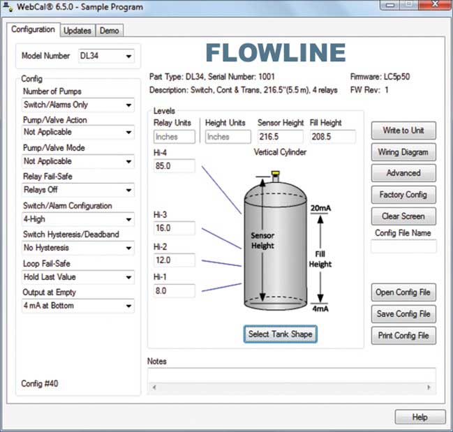
WebCal Software
The PC utility allows you to easily configure and test compatible level sensors to your requirements.
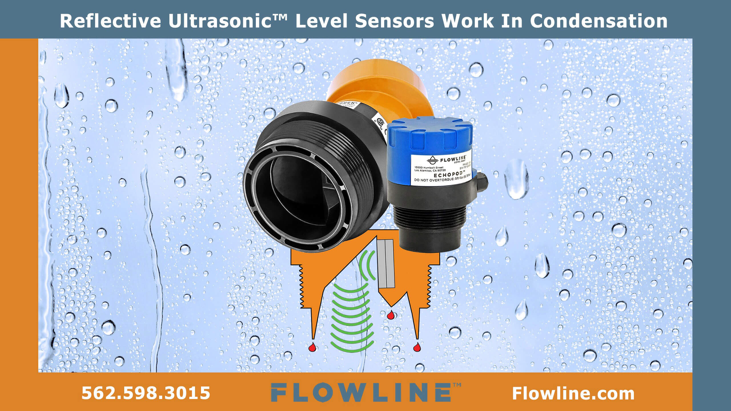
Technology Videos
Watch and learn about our 80 GHz radar, reflective ultrasonic and guided wave level sensor technologies.
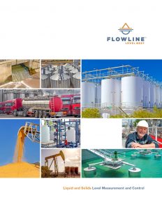
Level Brochure
Request your free copy of our liquid and solids level measurement and control solutions brochure.
![]()
10500 Humbolt Street
Los Alamitos, CA 90720 USA
562.598.3015 p
562.431.8507 f
level.solution@flowline.com


